sancharFirst Logo
    Spectroscopic Techniques
  • UV-Visible Spectroscopy

    • a) Principle

    • In this technique, the light is absorbed by the analytes in the UV and the visible region of the electromagnetic spectrum.
    • Light in this region excites the electrons in the atom of an analyte from the ground state to the higher energy levels, which results in absorbance at specific wavelengths for each molecule.
    • This absorbance is defined as the negative logarithm of the transmittance (the ratio of the intensity of the light entering the sample to that of the intensity of the light exiting the sample).
    • It is proportional to the path length (the distance travelled by light) and the concentration (in terms of molarity) as given by the Beer-Lamberts Law which is:


      A= ε*c*l


      Where,

      A= absorbance of the analyte
      ε= molar absorptivity coefficient of the substance
      c= concentration of the analyte
      l= path length
       

    • b) Instrumentation:


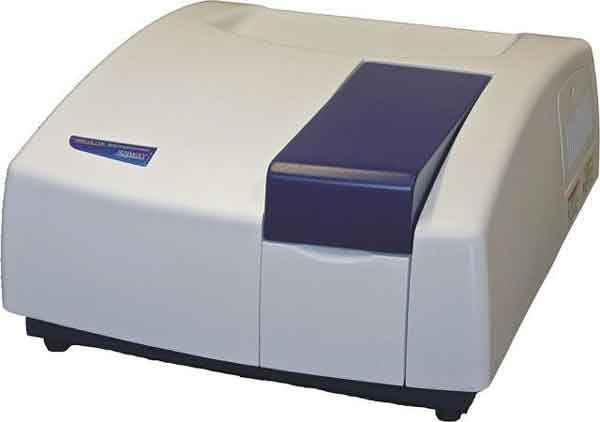
    • The UV visible spectrophotometer comprises of the following:
      • Source:
        • It provides the radiation which falls on the analyte.
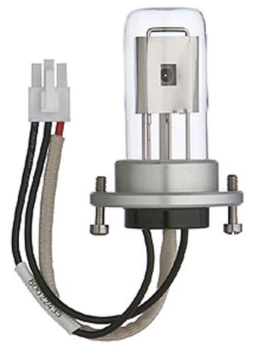
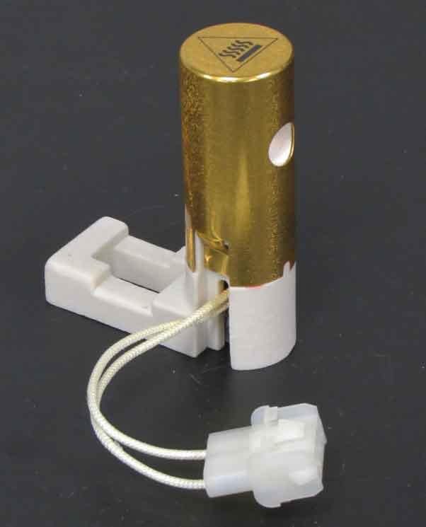
        • Generally, a deuterium or a hydrogen lamp is used for the UV region, while a tungsten lamp is used for the visible region.


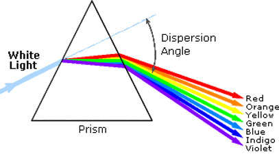
    • Monochromator:
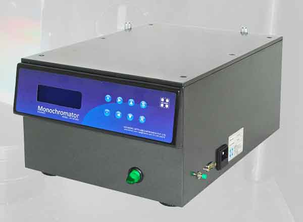
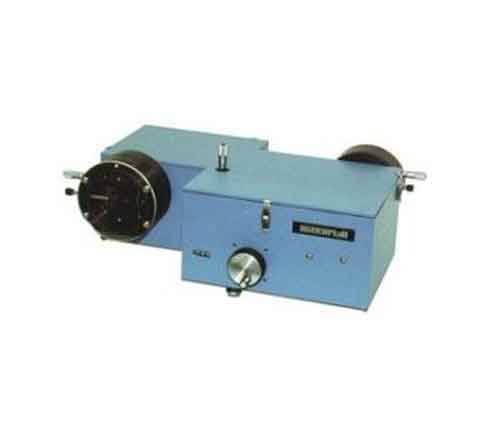
      • It isolates and filters light of a single wavelength.
      • Prisms or diffraction gratings are generally used as monochromators.


    • Sample Holder/Cuvette:-
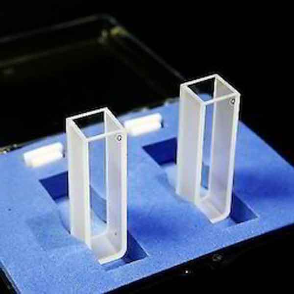
      • It is used to hold the analyte under study and introduce it into the light path.
      • For wavelengths above 310 nm, glass and plastic cuvettes are used while quartz or silica cuvettes are used when measuring absorption of UV wavelengths (up to 180 nm only)
      • Detectors:-
        • Detectors are used to convert the light signals into an electronic signal.
        • The most common detectors used for UV-visible spectroscopy are the photomultiplier tube and the photodiode array detector.
      • Applications:-
        • Quantitative Analysis
        • Detection of Impurities
        • Structural Elucidation
        • Qualitative Analysis
        • Dissociation constants of acids and bases
        • Chemical kinetics
        • Molecular weight determination
  • Fourier Transform Infrared Spectroscopy (FTIR)
    • Principle
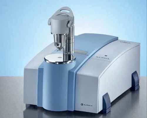
    • In FTIR, the infrared light passes through the Michelson’s Interferometer.
    • This interferometer has moving mirrors which change the optical path difference to produce a change in the phase difference which creates interference light.
    • The intensity of this interference light is recorded in an interferogram.
    • Instrumentation:
    • Source:
    • It provides radiation in the mid and near IR regions.
    • For the mid-IR regions (2-25 µm or 5000-400 cm-1), silicon carbide heated up to 1200 K.
    • For the shorter wavelengths of the near-IR regions (1-2.5 µm or 10000-4000 cm-1), a high temperature source like the tungsten halogen lamp is used.
    • For the far-IR, especially for wavelengths greater than 50 µm (200 cm-1), a mercury discharge lamp is used.


    • Detectors:
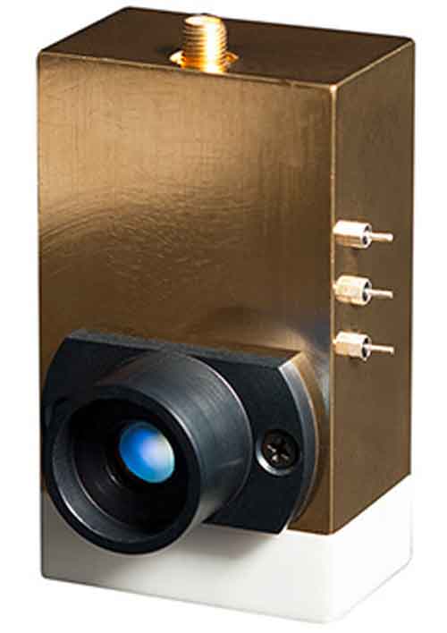
    • Mid-IR spectrophotometers generally use pyroelectric detectors consisting of compounds like deuterated triglycine sulphate (DTGS) or lithium tantalate (LiTaO3).
    • Uncooled indium gallium arsenide photodiodes or DTGS are commonly used in near-IR systems.
    • Very sensitive liquid helium cooled silicon or germanium bolometers are used in the far-IR regions.


    • Michelson’s interferometer:
    • It consists of a fixed mirror, a moving mirror and a beam splitter.
    • It is the most important part of an FTIR spectrophotometer.
    • It provides the interference pattern of light to the detector which converts it into an interferogram.


    • Applications:
    • Microscopy and imaging- Histopathology (analyzing tissue sections) and checking the homogeneity of pharmaceuticals
    • Nano-FTIR- Small viruses and protein complexes
    • FTIR as detector in chromatography- GC-FTIR and gel permeation chromatography
    • Thermogravimetric analysis- infrared spectrophotometry (TG-IR)
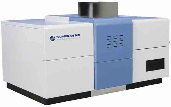
  • Atomic Absorption Spectroscopy (AAS)
    a) Principle:
    • This technique is based on the fact that free atoms (gaseous) created in an atomizer can absorb radiation at a specific frequency.
    • It quantifies the absorption of gaseous atoms in the ground state.
    • The atoms absorb UV or visible light and move to a higher energy level.
    • The concentration of analyte is determined from the amount of absorbed radiation.

    • Instrumentation:
    • Source:
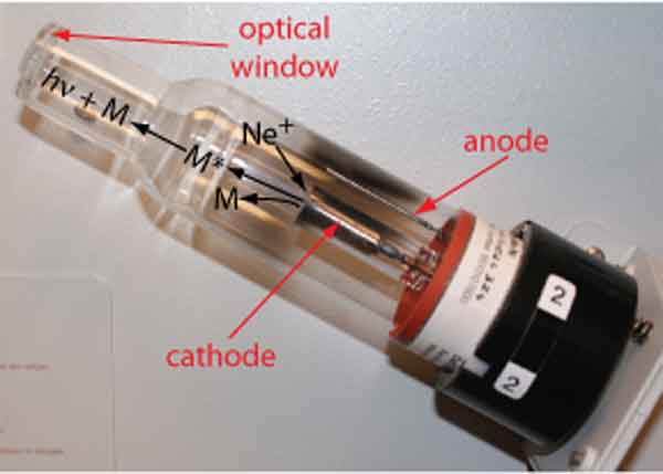
    • The most commonly used source of radiation in AAS is the hollow cathode lamp.
    • It is made of a tungsten anode and the cathode is made up of the element to be analysed.
    • These are sealed in a hollow glass tube filled with neon or argon.
    • Each element has its own unique lamp to be used for analysis.


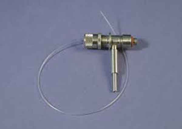
      • Nebulizer:
      • It is a component of AAS that serves three purposes:
      • Suck up the liquid samples at controlled rates.
      • Create a fine aerosol spray for introducing in the flame.
      • Mix the aerosol and the fuel and the oxidant thoroughly.


    • Atomizer:
    • The elements to be analysed have to be in an atomic state.
    • Atomization is the separation of particles into molecules and breaking molecules into atoms.
    • This is done by exposing the molecules to a high temperature in either a flame or a graphite furnace.
    • The atomizers thus are of two types:
    • Flame atomizer- oxidant gas and fuel gas used to create flame. For liquid or dissolved samples
    • Graphite furnace- Samples deposited on a small graphite tube and heated. Samples heated using a high current power supply.
    • Monochromator:
    • It is an important component of AAS, used to select a specific wavelength absorbed by the sample and to exclude all others.
    • This helps to detect the specific element in the analyte in the presence of other elements.
        • Detector:
        • The light from the monochromator goes to a detector, generally a photomultiplier tube.
        • It converts the light signal obtained from the monochromator into an electrical signal which is proportional to the intensity of the absorbed light.
        • This signal is amplified further by an amplifier and then either displayed on the readout or further fed to the data station for printout.


        • Applications:
        • In forensic sciences- Hair analysis for heavy metals, trace elements in fibres, etc.
        • Pharmaceuticals-Drug development, quality control
        • Nanomaterial research
        • Environmental monitoring- Soil, water, air
        • Food safety and nutritional labelling.
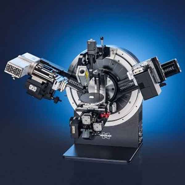
  • X-Ray Diffraction (XRD)
    • a) Principle
    • X-rays are generated by a cathode ray tube and then filtered to produce monochromatic radiation.
    • This radiation is then focused and directed towards the sample.
    • The interaction between these incident x-rays and the sample produces constructive interference which occurs only if the conditions satisfy the Bragg’s law (nλ= 2dsinθ)
    • These diffracted rays are then detected, processed and counted.
    • Instrumentation:
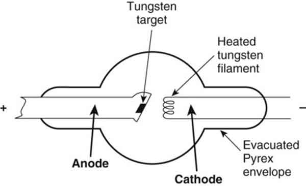
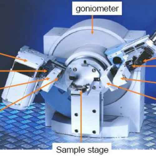
    • X-Ray Tube:
    • It is a cathode ray tube with a filament which is heated to produce electrons.
    • These electrons are then accelerated by applying voltage and then the target material is bombarded.


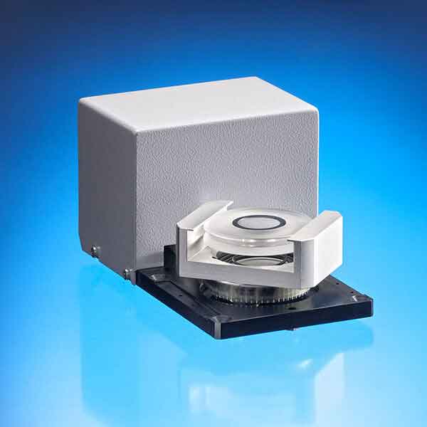
    • Sample Stage:
    • The sample holder keeps the sample aligned in the beam.
    • It also controls the movement of the sample.


    • Detector:
    • It processes and records the X-ray signal. 
      It also converts this signal into a count rate which is then displayed to a device such as a printer or a computer monitor.


    • Goniometer:
    • The geometry of a XRD is such that the angle of rotation for the sample is θ, while the X-ray detector which is mounted to an arm to collect the diffracted x-rays rotates at an angle of 2θ.
    • To maintain this angle, an instrument is used which is called the goniometer.


      • Applications:
      • Identification of unknown crystalline materials
      • Sample purity
      • Determination of crystal structure
      • Quantitative analysis
      • Identification of fine grained minerals such as clay that are difficult to determine optically.

  • Go to the top of the page

    Go to Main Menu